THE BASICS OF POWER FACTOR CORRECTION CAPACITORS
WHY DO WE NEED THEM?
Induction motors use electromagnets to produce magnetic fields for their operation. Their magnetizing inductance results in "lagging" power factor (PF), where the consumed current lags the applied voltage. Rated PF of efficient electric machines can be up to 0.85, which is not so bad. The problem is in practice they are underloaded much of the time and sometimes even unloaded. The PF of an idle motor can be as low as 0.1.
WHERE TO CONNECT THE CAPS?
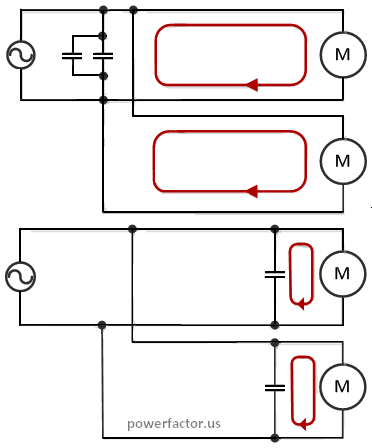 It is common to place parallel power factor correction capacitor banks in a single location near the service meters. This method features lower installation cost and provides compensation of the total PF of entire facility. Note however that the caps reduce only upstream reactive power. Therefore the above placement does not affect the currents flowing to the motors via individual branches. The diagram to the right shows in red the circulation of reactive power for different placement methods. For simplicity this diagram shows a single phase input. In practice, most industrial motors are 3-phase.
To reduce the currents in the downstream cables and associated ohmic losses, individual caps can be connected direcly by the loads. This method shortens the path of kVAR. It can also improve the motors efficiency by reducing voltage drop in the wiring.
POSSIBLE PROBLEMS AND HOW TO AVOID THEM
-
Harmonic resonance.
Nonlinear devices generate harmonic current. When we connect a capacitance "C" to an inductance "L", we create a circuit with resonance frequency Fres=1/(2π√LC). If "Fres" approaches any of the existing harmonics, it will be amplified. This can cause various problems including a catastrophic failure. To address this issue you can install a small inductor in series with the PFC capacitor, which creates a so-called shunt harmonic filter. -
Self-Excitation.
Excessive capacitance will cause over-compensation of motor reactance. This can create over-voltage condition for both the caps and motors. That's why the PFC capacitors should be sized to compensate not more than 95% of the no-load kVAR (see our calculator for sizing information).
REFERENCES:
Power factor correction guide