THE BASICS OF ACTIVE POWER FACTOR CORRECTION
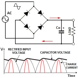 With that, in linear PSU the rectifier is connected via a low-frequency transformer, while in off-line switch-mode PSU it is fed from the AC input. In both cases, once "Co" is charged to nearly peak of rectified voltage, most of the time the diodes will be reversed biased and will not conduct. Therefore, such a PSU will draw power from the line in short pulses only when the instantaneous input voltage exceeds the voltage across the capacitor. This produces harmonics whose level can exceed an applicable standard (such as EN61000-3-2) and adversely affect other users.
In order to consume continuous sine-like current over the entire AC cycle, we can place an inductance before "Co". In passive PFC the inductor is large and uncontrolled. It typically corrects the PF to 0.7-0.85.
 In practice, a passive method is used only in small PSU (usually below 100W), when high PF is not required and regulation of DC-link is not necessary.
In most other application an active method is used. This is a conceptual schematic of active PFC boost converter. The inductor "L" here is controlled by a solid state switch (denoted "Q"). This switch is driven ON and OFF by the control circuit at a frequency "F" much higher than the mains frequency. Let's review how this circuit operates. During on-time "ton" the current in the inductor increases by ΔI+=Vin×ton/L. When the switch opens, the voltage across "L" reverses and it is releasing all or portion of accumulated energy via the diode "D". During the off-time "toff" inductor current decreases by ΔI-=(Vo-Vin)×toff/L. The net change during one period "T" is ΔI=ΔI+-ΔI-=(Vin-Vo+D×Vo)/LF, where D=ton/T- duty cycle, F=1/T. We can see that by varying duty cycle "D" we can vary ΔI. If we do it properly, we can synthesize a desired I(t) shape.
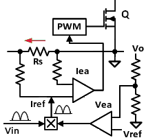 Here is a simplified block diagram of PFC control. Of course, commercially available PFC controllers contain many more functional blocks, but our example is sufficient to illustrate the basics of the operation. You can see an example of a complete PFC schematic here. The depicted circuit contains two error amplifiers- a slow one for voltage (Vea) and a fast one for current (Iea). A replica of rectified input waveform "Vin" is fed into the multiplier, which produces the programming signal Iref for Iea. The latter monitors the current via a sense resistor Rs and compares it to Iref. By varying control signal to pulse-width modulator (PWM), Iea forces average value of current to follow the shape of the mains voltage. The Vea monitors Vo via a divider and compares it to reference Vref. The error signal from Vea scales multiplier output up or down without changing its sine wave pattern. As the result, this circuit can perform two tasks simultaneously: it creates sine-like current and regulates the bus voltage Vo. The described method allows the designers to achieve PF as high as 0.99. Note that the described power factor correction technique addresses only line-frequency harmonics. You still need an EMI filter to reduce high-frequency components generated by switching mode operation of the power converters. This filter however may cause some negative effects. Particularly, its differential-mode inductors and across-the-line capacitors can introduce certain displacement angle between "Vin" and "I", which is not corrected by the downstream PFC circuit. This effect may be unimportant if you have to comply only with EN61000-3-2, but could be an issue if in your application you also need to meet certain minimum PF limit.
REFERENCES:
Practical Power Supply Design Handbook- topologies, magnetics, feedback loop, equations.
Power factor correction handbook.