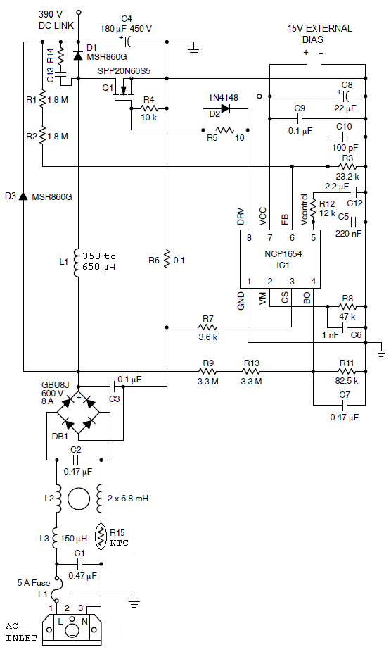
300 WATT POWER FACTOR CORRECTION CIRCUIT

Controller IC1 operates at a fixed frequency 66 kHz and implements average current mode control. It senses input voltage via the network consisting of R9, R11, R13, and C7. DC output is monitored via the divider R1, R2, R3. The low-frequency component of the voltage across resistor R6 replicates input AC current.
The controller drives high-voltage MOSFET Q1, which in turn energizes inductor L1. For continuous conduction mode the value of inductance L1 has to be above certain threshold (see CCM boost design equations and calculator). My analysis shows that in this circuit 350 uH value is sufficient, although the On-Semi datasheet recommends 650 uH.
Discharged capacitor C4 initially acts as a short circuit. That's why without inrush current limiter R15, you may blow either the fuse or resistor R6 upon initial power up. Likewise, without diode D3, starting surge current can saturate L1, which can then blow up Q1 or R6.
The network R14-C13 is used to reduce dV/dt of Q1 and to lower reverse recovery current of D1. This usually also helps to get rid of parasitic oscillations. This snubber may be unnecessary if you use a silicon-carbide boost diode.
The design procedure of this power stage is described in details in the application note AND8322.
