WHAT IS POWER FACTOR?
|
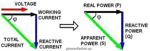
Power factor (PF) by definition is a ratio between working power P (watts) and apparent power S (volt-amps): PF = P/S = watts/Vrms×Irms It is a quantity that tells us how effectively your device utilizes electricity. Watts represent actual or real power. The volt-amp product "VA" is called apparent power because it is just a mathematical quantity which has no real physical meaning. For an easy explanation of the physical meaning of PF, let's consider a simple example. Suppose you connect an ideal capacitor "C" across an AC line. Since AC voltage is continuously changing its polarity, half of the time this cap will be charging from the input and half of the time it will be returning the stored energy back to the source (see animation video below). Courtesy of Joe Wolfe at Physclips Project at UNSW. In circuits analysis a sinewave signal can be represented by a complex number (called phasor) whose modulus is proportional to the magnitude of the signal and angle equals to its phase relative to some reference. In linear circuits PF= cosφ, where φ is angle between voltage and current phasors. These vectors and corresponding ones for active and reactive components of power can be presented by a triangle (see the diagram below). Of course, voltage is an electric field and current is a flow of electrons, so the so-called angle between their phasors is nothing more than another mathematical quantity. By convention, inductive load create positive volt-amp reactive (VARs). It is associated with so-called "lagging" power factor because current is behind the voltage. |
 Likewise, capacitive load create negative VARs and "leading" power factor.
Inductors and caps are not the only reasons of low PF. Except for ideal R, L and C, all practical electrical circuits are non-linear, particularly because of the presence of active components, such as rectifiers. In such circuits current I(t) is not proportional to the voltage V(t), i.e. even if V(t) is a pure sinusoid, I(t) will be periodic but non-sinusoidal. According to Fourier theorem, any periodic function is a sum of sine waves with frequencies that are whole multiples of the original one. These waves are called harmonics. It can be shown that they don't contribute to net energy transfer, but increase Irms and reduce PF. When voltage is sinusoidal, only first harmonic I1rms can deliver real power. However its amount depends on the phase shift between I1rms and V. These facts are reflected by the general formula for PF: PF=(I1rms/Irms)×cosφ The first term in this equation represents the distortions, the second one- the reactances. If you want to see how this formula is derived, check out math analysis of AC power. |